Congratulations! Your new Ideal Logic Combi 30 offers efficient heating and hot water; this manual guides you through operation and maintenance procedures.
This comprehensive guide assists in understanding and operating your boiler, ensuring safe and economical performance, as detailed in the provided PDF instructions.
The Logic Combi2 delivers central heating and instant hot water, featuring automatic ignition and a fan, as outlined within the installation and servicing documentation.
What is a Combination Boiler?
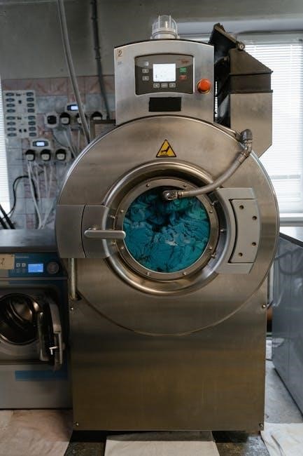
Combination boilers, often called “combi” boilers, are incredibly efficient heating systems that provide both central heating and on-demand domestic hot water within a single, compact unit. Unlike traditional systems requiring separate boilers and storage tanks, a combi boiler heats water directly from the mains as it flows through, eliminating standby heat loss and saving valuable space.
The Ideal Logic Combi 30 exemplifies this technology, offering “instantaneous” hot water – meaning you don’t wait for a tank to fill. This is achieved through a high-output heat exchanger and powerful fan, as described in the Logic Combi2 documentation.
Essentially, a combi boiler simplifies your home heating setup, offering convenience and energy efficiency. It’s a popular choice for modern homes, and understanding its functionality is key to maximizing its benefits, as detailed in the Ideal Logic installation and servicing instructions.
Key Features of the Ideal Logic Combi 30
The Ideal Logic Combi 30 boasts several key features designed for efficiency and user convenience. It provides full sequence automatic ignition and a modulating fan, ensuring optimal performance and reduced energy consumption, as highlighted in the product documentation.
This boiler is known for its compact design, making it suitable for various installation locations. The user-friendly control panel, detailed in the manual, offers intuitive operation and clear display indicators.
Furthermore, the Logic Combi 30 offers a high hot water flow rate, delivering instant hot water on demand. Its compatibility with external control devices (when recommended) adds flexibility. Regular servicing, as outlined in the PDF manual, ensures longevity and peak performance.
Boiler Model Numbers & Variations (S30, ES 30)
The Ideal Logic range includes variations like the S30 (GC No. 41 796 88) and the ES 30 (GC No. 47 349 01), each designed for specific heating and hot water demands. Downloading the correct manual, readily available as a PDF, is crucial for proper operation and maintenance.
While sharing core features, these models may differ slightly in their specifications and installation requirements. The ES 30, for example, is a combi boiler, providing both central heating and instant hot water. Always refer to the manual corresponding to your specific model number.
Understanding these distinctions ensures you follow the correct instructions for installation, servicing, and troubleshooting. Accessing the appropriate manual guarantees safe and efficient operation of your Ideal Logic boiler.

Safety Precautions
Essential! Strictly follow all instructions in this booklet for safe boiler operation; heed warnings regarding electricity and potential carbon monoxide risks.
Do not connect unauthorized external controls, and ensure qualified personnel handle all installation and servicing procedures, as detailed in the manual.
General Safety Warnings
Crucially, this appliance must be installed and serviced by a qualified and competent installer, adhering to all relevant regulations and instructions. Incorrect installation can lead to unsafe operation and potential hazards.
Always disconnect the electricity supply before carrying out any maintenance or cleaning procedures. Never attempt repairs yourself; contact a qualified service engineer. Ensure adequate ventilation in the boiler room to prevent the build-up of fumes.
This boiler is designed for indoor use only and must be protected from frost and extreme weather conditions. Do not obstruct ventilation openings or cover the appliance. Regularly inspect the flue for any signs of damage or blockage.
Keep flammable materials away from the boiler. Children and vulnerable individuals should be supervised around the appliance. Familiarize yourself with the location of the emergency shut-off valves for both gas and water supplies.
Carbon Monoxide Risks
Carbon monoxide (CO) is a colorless, odorless, and highly poisonous gas. A faulty or improperly installed boiler can produce CO, posing a severe health risk, even leading to death. Regular servicing by a qualified engineer is vital to ensure safe operation and prevent CO leaks.
Install a CO detector that meets BS EN 50292 standards in the same room as the boiler, following the manufacturer’s instructions; Test the detector regularly to confirm it’s functioning correctly. Be aware of the symptoms of CO poisoning: headache, dizziness, nausea, breathlessness, and confusion.
If a CO detector alarms, immediately turn off the boiler, open windows and doors, and evacuate the premises; Contact emergency services and a qualified gas engineer. Never ignore a CO alarm. Ensure the flue is unobstructed and correctly fitted.
Any changes to the boiler or flue system must be carried out by a qualified professional. Do not attempt to modify the appliance yourself.
Electrical Safety Instructions
Before undertaking any electrical work, always isolate the boiler from the electricity supply by switching off the appropriate circuit breaker or removing the fuse. Do not connect external control devices unless specifically recommended in this manual or by Ideal Heating in writing. Incorrect wiring can cause damage or pose a safety hazard.
Ensure the electricity supply specifications match those detailed in the installation guide. The appliance must be earthed. Any electrical connections must comply with current regulations. Qualified personnel only should perform electrical work on the boiler.
Inspect wiring for damage before connecting. Do not use damaged cables or connectors. Refer to the wiring diagram provided in the manual for correct connections. Ensure all connections are secure and properly insulated. Failure to adhere to these instructions could result in electric shock or fire.

Installation Guide Overview
Qualified installers are essential for correct setup; this guide details unpacking, location requirements, and connections for the Ideal Logic Combi 30 boiler.
Strictly follow the installation instructions for safe and economical operation, covering plumbing, gas, and electrical aspects of the boiler system.
This document provides comprehensive installation and servicing instructions, ensuring optimal performance and adherence to safety standards.
Qualified Installer Requirement
Crucially, the installation of the Ideal Logic Combi 30 must be carried out by a qualified and competent installer, adhering to all current regulations and industry best practices. This isn’t merely a recommendation; it’s a fundamental safety requirement stipulated within the installation and servicing instructions.

Attempting to install this boiler without the necessary qualifications could lead to unsafe operation, potential gas leaks, carbon monoxide poisoning, and invalidation of the warranty. A qualified installer possesses the expertise to correctly connect the gas and water supplies, ensure proper ventilation, and configure the electrical connections according to the wiring diagram.
They will also be familiar with the specific requirements for condensate pipe installation and will be able to perform the initial start-up procedure and safety checks. Always verify the installer’s credentials before commencing any work. Refer to the full PDF manual for detailed guidance and compliance information.
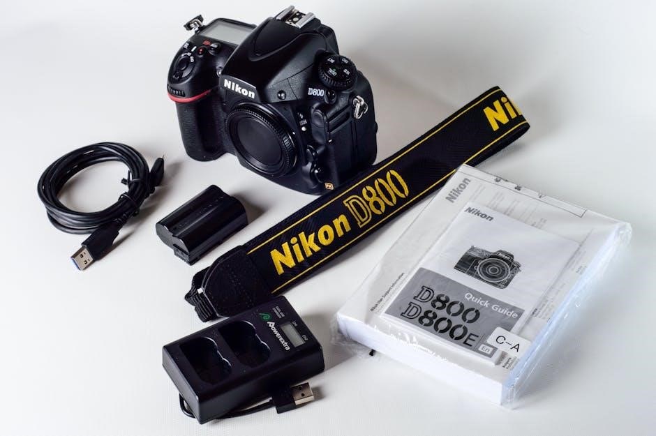
Unpacking and Inspection
Upon delivery of your Ideal Logic Combi 30, carefully unpack the unit and thoroughly inspect it for any signs of damage incurred during transit. This inspection should be performed immediately, before the boiler is installed or signed for with the delivery company.
Check the exterior casing for dents, scratches, or other visible damage. Verify that all components listed in the accompanying documentation are present, including the boiler itself, any supplied fixings, and relevant manuals. Any discrepancies or damage must be reported to the supplier immediately.
Do not attempt to install a damaged boiler. Retain all packaging materials until you are satisfied that the unit is functioning correctly. Refer to the detailed PDF manual for a complete list of included components and a visual guide to aid in the inspection process.
Boiler Location Requirements
Selecting the correct location for your Ideal Logic Combi 30 is crucial for optimal performance and safety. The boiler should be installed in a well-ventilated area, ideally within a purpose-built utility room or kitchen, adhering to all local building regulations.
Avoid locations prone to freezing temperatures, as this can damage the boiler’s components. Ensure sufficient space around the unit for servicing and maintenance access – the manual specifies minimum clearances of 30mm on all sides, with a height of 970mm.
The installation area must have a suitable floor capable of supporting the boiler’s weight, and appropriate flue and condensate pipe runs must be feasible. Refer to the detailed PDF manual for specific guidance on permissible locations and any necessary ventilation requirements.
Plumbing Connections
Proper plumbing is essential! Connect the water, gas, and condensate pipes according to the manual, ensuring secure fittings and adherence to regulations.
Carefully follow the instructions for water supply, gas supply, and condensate pipe installation, as detailed in the comprehensive PDF documentation.
Water Supply Connections
Ensuring a reliable water supply is crucial for the Ideal Logic Combi 30’s operation. The boiler requires a connection to the mains cold water supply, with adequate pressure for optimal performance. Before connecting, thoroughly flush the water pipes to remove any debris or contaminants that could damage the boiler’s internal components.
The manual details specific requirements for pipe diameter and materials, typically recommending 15mm copper or plastic pipes compliant with relevant standards. A stopcock should be installed upstream of the boiler to allow for isolation during maintenance or emergencies. It’s vital to check for any leaks after making the connections, tightening fittings as necessary.
Consider incorporating a filter to further protect the boiler from sediment. The instruction manual provides diagrams illustrating the correct connection points and recommended practices. Incorrect water supply connections can lead to reduced efficiency, increased noise, or even boiler failure, so meticulous attention to detail is paramount.
Gas Supply Connections
Gas supply connections must be carried out by a Gas Safe registered engineer, strictly adhering to the Ideal Logic Combi 30’s installation manual. Incorrect gas connections are extremely dangerous and can lead to gas leaks, explosions, or carbon monoxide poisoning.
The boiler is designed to operate with either Natural Gas (NG) or Liquefied Petroleum Gas (LPG), but a conversion kit is required to switch between the two. The manual clearly outlines the procedure for this conversion, which should only be performed by a qualified professional. Ensure the gas supply pressure is within the specified range detailed in the documentation;
A gas shut-off valve should be installed upstream of the boiler for isolation purposes. All gas connections must be leak-tested using a suitable leak detection fluid. The instruction manual provides detailed diagrams and safety warnings regarding gas supply connections, emphasizing the importance of compliance with all relevant regulations.
Condensate Pipe Installation
Correct condensate pipe installation is crucial for the efficient and safe operation of the Ideal Logic Combi 30. As a condensing boiler, it produces acidic condensate which must be safely drained away.
The manual details specific requirements for the condensate pipe material, diameter, and gradient. It must be installed with a continuous downward slope to prevent blockages and ensure proper drainage. Avoid sharp bends and ensure the pipe terminates in a suitable location, protected from freezing.
Installation must comply with local building regulations. The instruction manual emphasizes the importance of using appropriate fittings and seals to prevent leaks. A trap should be installed within the condensate pipe run to prevent flue gases from being drawn back into the boiler. Refer to the PDF for detailed diagrams and warnings regarding condensate pipe installation.
Electrical Connections
Carefully follow the wiring diagram in the manual, ensuring correct electricity supply specifications are met for safe operation of the Ideal Logic Combi 30.
This appliance requires adherence to electrical safety instructions detailed within the comprehensive PDF documentation provided with your new boiler installation.
Wiring Diagram
The wiring diagram is crucial for correct and safe electrical connection of the Ideal Logic Combi 30. It details the specific connections required for the appliance to function optimally and safely, and is found within the comprehensive installation manual.
Always disconnect the electricity supply before attempting any wiring connections. The diagram illustrates the live, neutral, and earth connections, alongside any connections for external control devices, if applicable. Do not connect external controls unless specifically recommended in the manual or by Ideal Heating in writing.
Pay close attention to the color coding of the wires and ensure they are securely connected to the appropriate terminals. Incorrect wiring can lead to malfunction, damage to the boiler, or even pose a safety hazard. Refer to the manual’s detailed illustrations and instructions for precise guidance. If unsure, consult a qualified and certified heating engineer.
The diagram also indicates the fuse rating required for the appliance, ensuring adequate protection against electrical faults. Using an incorrect fuse rating can compromise safety.
Electricity Supply Specifications
The Ideal Logic Combi 30 requires a specific electricity supply to operate correctly and safely. It is essential that these specifications are strictly adhered to during installation. The appliance is designed for 230V/50Hz operation, standard in most UK households.
This appliance must be earthed. The manual details the necessary earthing connection requirements for optimal safety; Ensure the electrical supply is capable of providing sufficient power to the boiler, particularly during peak demand. Incorrect voltage or frequency can damage the appliance.
Always disconnect the electricity supply before carrying out any maintenance or servicing. The manual specifies the required fuse rating for the boiler, protecting against electrical faults. Using an incorrect fuse rating can compromise safety. The electrical connections must be made by a qualified and competent person, adhering to all relevant safety regulations.
Refer to the installation manual for detailed diagrams and instructions regarding the electrical connections.
Operating Instructions
Begin with the initial start-up procedure, carefully following the manual’s guidance for safe operation. Adjust temperature settings as needed for comfort and efficiency.
Control hot water output using the designated controls, ensuring consistent and reliable performance, as detailed in the comprehensive user manual.
Initial Start-Up Procedure
Before initiating the start-up, ensure the boiler has been correctly installed by a qualified professional, adhering to all safety regulations and manufacturer’s instructions. Verify the gas and water supplies are turned on and that the system is adequately pressurized, typically between 1 and 1.5 bar, as indicated on the pressure gauge.
To begin, locate the power switch, usually situated on the boiler’s control panel, and switch it to the ‘on’ position. The boiler will then initiate its self-diagnostic sequence, which may take a few moments. Observe the display panel for any error codes; consult the troubleshooting section of the manual if any appear.
Once the self-diagnostic is complete, the boiler should be ready for operation. Turn on a heating radiator valve and then request hot water from a tap. The boiler will ignite and begin to deliver heat or hot water. Monitor the operation closely during the initial start-up to ensure everything functions correctly. Refer to the full PDF manual for detailed guidance.
Setting the Temperature
Adjusting the central heating temperature is achieved via the control panel. Utilize the up and down arrow buttons to select your desired temperature, displayed in degrees Celsius. The boiler offers a wide temperature range, allowing for personalized comfort levels. Remember that lower temperatures contribute to energy savings.
For hot water temperature control, navigate to the hot water setting on the control panel. Similar to central heating, use the arrow buttons to adjust the desired temperature. Be cautious when setting hot water temperatures, especially in households with young children or vulnerable individuals, to prevent scalding.
The Ideal Logic Combi 30 often features pre-set temperature profiles for convenience. Consult the full PDF manual for details on utilizing these features and optimizing your boiler’s performance. Regularly review and adjust temperatures based on seasonal changes and personal preferences.
Hot Water Control
The Ideal Logic Combi 30 provides on-demand hot water, eliminating the need for a storage tank. Hot water is activated when a tap is opened, and the boiler modulates its output to maintain a consistent temperature. Control is primarily managed through the boiler’s control panel.
Adjusting the hot water temperature is crucial for comfort and safety. Use the designated buttons on the control panel to increase or decrease the temperature, ensuring it’s suitable for your household’s needs. Refer to the full PDF manual for specific temperature recommendations.
Some models may offer features like pre-heating or comfort modes, allowing for faster hot water delivery. Explore these options within the boiler’s settings. Always prioritize safety by setting a temperature that prevents scalding, particularly for vulnerable users. Proper hot water control maximizes efficiency.

Understanding the Control Panel
The control panel displays vital information using indicators and symbols; it’s your interface for operation and troubleshooting, as detailed in the manual.
Error codes provide diagnostic information, aiding in quick problem identification and resolution, outlined within the comprehensive PDF documentation.
Display Indicators and Symbols
The Ideal Logic Combi 30’s control panel utilizes a range of display indicators and symbols to communicate the boiler’s status effectively. Understanding these is crucial for proper operation and troubleshooting. A steady flame symbol indicates normal operation, signifying the boiler is actively heating or providing hot water. A flashing flame suggests a call for heat is in progress.
Various symbols relate to error conditions. A specific code, displayed numerically, will pinpoint the issue, referencing the detailed troubleshooting section within the full PDF manual. The water temperature indicator shows the current central heating water temperature, while the hot water tap symbol indicates hot water is being drawn.
Additional symbols may represent frost protection activation, low water pressure, or other system alerts. Always consult the manual for a complete and accurate interpretation of each symbol, ensuring you can respond appropriately to any displayed message. Ignoring these indicators could lead to inefficient operation or potential damage.
Error Codes and Troubleshooting
The Ideal Logic Combi 30 utilizes error codes to diagnose potential issues, displayed on the control panel. These codes are essential for effective troubleshooting, and a comprehensive list is provided within the PDF manual. Common codes relate to ignition failure, gas supply problems, or low water pressure.
Before attempting any repairs, consult the manual’s troubleshooting section. Simple solutions, like checking the gas supply or resetting the boiler, may resolve the issue. However, do not attempt complex repairs yourself; always engage a qualified heating engineer.
The manual details specific actions for each error code, guiding you through a logical diagnostic process. Ignoring error codes can lead to further damage or unsafe operation. Remember, safety is paramount; if unsure, contact a professional. Referencing the manual ensures correct identification and resolution of any boiler fault.

Maintenance and Servicing
Regular servicing, as detailed in the manual, is crucial for efficiency and longevity; cleaning and frost protection measures are also outlined for optimal performance.
Adhering to the manual’s schedule ensures safe and economical operation, preventing potential faults and maintaining warranty validity, as per Ideal Heating guidelines.
Regular Servicing Schedule
Annual servicing by a qualified and Gas Safe registered engineer is essential for maintaining the efficiency and safety of your Ideal Logic Combi 30. The manual emphasizes this requirement to ensure optimal performance and longevity of the appliance. A service involves a comprehensive check of all components, including the burner, heat exchanger, flue, and safety devices.
Ideal Heating recommends a service every 12 months, even if the boiler appears to be functioning correctly. This proactive approach can identify potential issues before they escalate into costly repairs. During a service, the engineer will also clean the boiler internally, removing any debris or build-up that could affect its operation. They will also check the flue for any blockages or corrosion, ensuring safe and efficient combustion.
Keep a record of all servicing carried out on your boiler, including the date, engineer’s name, and any work completed; This documentation is important for warranty purposes and can also be helpful if you ever need to contact Ideal Heating for support.
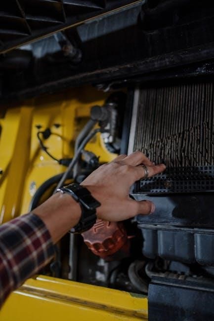
Cleaning the Boiler
Regular cleaning, though primarily performed during a service by a qualified engineer, involves some user-maintainable aspects. The Ideal Logic Combi 30 manual doesn’t detail extensive user cleaning, emphasizing professional servicing for internal components. However, the external casing can be wiped down with a damp cloth to remove dust and dirt – always ensure the boiler is switched off before cleaning.
Do not use abrasive cleaners or solvents, as these could damage the finish. Avoid getting water inside the boiler’s casing. The manual stresses that attempting to disassemble or clean internal components yourself is dangerous and will invalidate the warranty.

The engineer during the annual service will thoroughly clean the burner and heat exchanger, removing any build-up of combustion products. This ensures efficient operation and prevents potential issues. Maintaining a clean environment around the boiler also aids airflow and improves performance.
Frost Protection Measures
The Ideal Logic Combi 30 incorporates automatic frost protection, but preventative measures are crucial during prolonged cold spells. The manual details that the boiler will activate its pump if the return water temperature drops below 5°C, circulating warm water to prevent freezing. However, this relies on a stable electricity supply.
If a power outage is anticipated, or if the property will be unoccupied during freezing conditions, it’s vital to take additional steps. The manual recommends draining the system if extended periods of sub-zero temperatures are forecast. Consult a qualified heating engineer for assistance with this process.
Insulating exposed pipes is also highly recommended. Ensure adequate heating is maintained in the property, even at a reduced temperature, to prevent freezing. Regularly check vulnerable areas for signs of ice formation. Ignoring these precautions could lead to significant damage.